

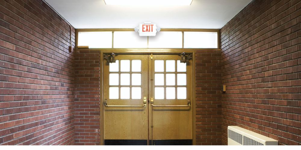
The Emergency Egress Testing & Maintenance Blueprint
To maintain full compliance with the NFPA 101 Life Safety Code across commercial paths of egress, facility managers must execute and document these mandatory testing protocols:
- The 30-Second Monthly Test: Conduct a manual or automated functional check every 30 days for a minimum of 30 seconds to ensure the internal emergency lamps instantly illuminate upon power loss.
- The 90-Minute Annual Test: Perform an exhaustive full-capacity duration test once a year, continuously draining the battery backups for 90 minutes to verify the system maintains required load voltages without dropping below 87.5% of nominal system voltage.
- Egress Performance Metrics: Emergency systems must activate within 10 seconds of a primary power interruption and maintain an initial average light level of 1.0 foot-candle along the floor path, tapering to no less than 0.6 foot-candle at the end of the 90-minute run.
- Remote Head Branch Linking: Maximize system efficiency by linking multiple passive remote accessory lighting heads to a single primary central battery pack enclosure via low-voltage wiring runs routed through standard junction boxes.
For building compliance managers, commercial facility directors, and electrical contractors, managing the infrastructure of a modern commercial property requires balancing everyday interior styling with strict architectural code enforcement. Within the realm of commercial and office lighting, emergency illumination and directional exit signage are not treated as basic decorative line items—they are strictly mandated life-safety systems. If secondary emergency infrastructure is neglected, a primary utility power failure can instantly plunge a facility into pitch darkness, causing severe panic, injuries, and catastrophic liability during an evacuation.
To eliminate these safety risks and standard installation failures, the National Fire Protection Association publishes the NFPA 101 Life Safety Code. This widely adopted building safety standard establishes baseline rules for the design, protection, and operational maintenance of designated paths of egress. Navigating these requirements demands a clear maintenance plan, strict adherence to testing schedules, and an optimized hardware layout. This technical guide outlines the legal safety regulations mandated under NFPA 101 and outlines a straightforward blueprint for testing emergency batteries and optimizing multi-fixture wiring paths.
1. The Path to Safety: Understanding Three-Part Egress Illumination
The core framework of NFPA 101 is designed to secure an unhindered, continuously lit path of travel out of a structure during an active fire, natural disaster, or localized grid failure. The life-safety code breaks a building’s evacuation path into three distinct physical components: the exit access (the initial corridor or aisle leading to a safety door), the exit itself (the protected transition zone, such as an enclosed fire stairwell), and the exit discharge (the final exterior pathway guiding occupants safely to a public way).

Under Section 7.9 of NFPA 101, emergency lighting must automatically illuminate this entire three-part egress system whenever primary utility power is interrupted by utility blackouts, blown internal fuses, or tripped circuit breakers. To satisfy both local fire codes and the National Electrical Code (NEC) and Safety Standards, the emergency lighting system must mechanically transition to backup power within exactly 10 seconds of a primary power loss. Furthermore, the system must be physically arranged so that the burnout of a single lamp bulb cannot leave any isolated section of an exit corridor in complete darkness.
2. Performance Standards: Foot-Candle and Uniformity Metrics
NFPA 101 moves past vague definitions of visibility by enforcing exact engineering metrics for brightness along the floor plane of an escape route. Emergency luminaires must deliver an initial average of 1.0 foot-candle (10.8 lux) of light along the exit access floor. As the battery backup drains over the legally mandated 90-minute operating window, the light output is permitted to drop slightly, but it must maintain a final average of no less than 0.6 foot-candle (6.5 lux) at the end of the duration test.
The code also enforces a strict maximum-to-minimum uniformity ratio to guarantee visual comfort during high-stress evacuations:
| Compliance Metric | Initial Standard (At Source Trip) | Terminal Standard (At 90 Minutes) |
|---|---|---|
| Minimum System Duration | — | 90 Continuous Minutes (1.5 Hours) |
| Average Lighting Level | 1.0 Foot-Candle (10.8 Lux) | 0.6 Foot-Candle (6.5 Lux) |
| Absolute Minimum Point | 0.1 Foot-Candle (1.1 Lux) | 0.06 Foot-Candle (0.65 Lux) |
| Max-to-Min Uniformity Ratio | Max-to-Min Ratio ≤ 40:1 | Max-to-Min Ratio ≤ 40:1 |
Enforcing a maximum uniformity ratio of 40:1 prevents dangerous lighting variations along an exit route. Without this standard, a corridor would alternate between intense, blinding glare zones and deep, pitch-black shadow pockets, causing confusion and slowing down building occupants during a rapid evacuation. All equipment selected to meet these targets must carry a third-party UL 924 listing, proving it is certified as emergency lighting and power hardware.
3. The Maintenance Blueprint: Mandatory Monthly and Annual Testing
Building owners are legally responsible for conducting and logging regular inspections of all egress hardware. The Authority Having Jurisdiction (AHJ)—such as a local fire marshal or municipal building inspector—can demand to see these maintenance records during any surprise code audit. To protect your facility from severe code violations, implement this straightforward testing blueprint:
The 30-Second Monthly Functional Test
Every 30 days, facilities must conduct a functional test on every emergency luminaire and exit sign for a minimum of 30 seconds. This check can be performed manually by pressing and holding the physical test switch on the side of the fixture housing, or automatically if the property utilizes self-testing, microprocessor-controlled fixtures. This monthly test verifies that the internal transfer switch operates properly, the battery engages instantly, and the LED lamps illuminate at the required brightness.
The 90-Minute Annual Duration Test
Once a year, battery-operated units must undergo an exhaustive full-capacity duration test. This requires completely disconnecting the main utility power feed to the emergency fixtures for a full 90 minutes. The test verifies that the rechargeable battery system can maintain the full electrical load for the entire 1.5-hour mandate without dropping below 87.5% of the nominal system voltage.

Preserving Written Compliance Records
Performing the tests is only half the battle; all diagnostics must be thoroughly documented. Contractors must maintain either a physical bound logbook or a verified digital compliance history file that clearly states the testing dates, individual unit identification codes, and pass/fail diagnostic readouts. These safety records must be kept completely up to date and readily accessible for review by the local fire marshal.
4. Exit Sign Geometry and Structural Mounting Rules
Alongside path lighting, Section 7.10 of NFPA 101 requires all building exits and directional access routes to be clearly identified with compliant exit signage. To prevent hesitation during smoky, high-stress conditions, the code enforces precise geometry rules for these signs:
- Letter Dimensions: The word "EXIT" must feature plainly legible letters at least 6 inches high, with a principal stroke width of no less than 3/4 inch and a letter width of at least 2 inches.
- Directional Chevrons: If the direct path to safety is not immediately obvious—such as a hallway that bends or forks—directional indicator arrows must be activated to show the correct direction of travel.

- Mounting Heights: Standard overhead signs must be mounted above doors or corridors so that the bottom of the enclosure hangs no more than 80 inches above the top edge of the egress opening.
- Floor Proximity Signage: In specific occupancies, low-level floor proximity exit signs must supplement overhead units. The bottom edge of these low signs must sit between 6 inches and 18 inches from the finished floor so they remain visible underneath rising columns of smoke.
5. Optimizing System Architecture: Branch-Linking Remote Accessory Heads
For large-scale commercial retrofits, specifying individual, self-contained "bug-eye" emergency lights with localized battery packs can lead to exceptionally high ongoing maintenance costs. Testing and replacing thousands of small lead-acid or nickel-cadmium batteries across a sprawling office floor requires an enormous amount of labor.
To streamline your layout, commercial facility designers implement a branch-linked system architecture. This configuration connects multiple passive remote accessory lighting heads to a single primary emergency fixture or central exit sign combo unit that houses an oversized, high-capacity battery pack enclosure.
To safely execute this branch-linked setup on the job site, follow these electrical steps:
- Calculate Total Wattage Capacity: Review the specification sheet of the primary emergency unit to determine its total remote load capacity in Watts. For example, if a primary fixture is rated for 15 Watts of total power and its internal lamps consume 5 Watts, it possesses a remaining 10-Watt capacity available to run secondary equipment.
- Match Remote Head Load: Ensure the cumulative wattage of the linked remote accessory heads does not exceed the remaining capacity of the primary central battery pack enclosure. Connecting two 5-Watt remote heads perfectly optimizes this load.
- Route Low-Voltage Runs: Run low-voltage wiring out of the primary fixture's internal transformer through pre-punched chassis knockouts. Route these low-voltage lines through standard electrical junction and outlet boxes out to the remote heads.
By grouping your remote fixtures onto a single primary battery hub, you significantly reduce the number of battery maintenance points across the building. This optimization allows facility directors to perform the required 30-second monthly checks and 90-minute annual duration tests from a single, centralized control enclosure, dramatically lowering compliance costs while fully safeguarding the property.
Conclusion: Protecting the Life-Safety Workplane
Successfully maintaining full compliance with the NFPA 101 Life Safety Code requires moving past basic, passive contractor installations and taking control of your facility's long-term maintenance needs. Trying to manage emergency lighting using unrecorded, manual switch checks leads to battery failure, system degradation, and severe zoning citations. By enforcing the strict 30-second monthly and 90-minute annual testing schedules, utilizing precision UL 924 listed components, and optimizing your layout via branch-linked remote heads running through code-compliant junction boxes, you can easily protect your project from code violations. This structured approach ensures your emergency fixtures activate instantly when needed, keeping your egress paths clear and fully illuminated for years to come.


