

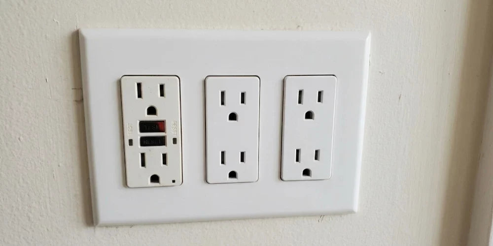
When wiring a workshop, finishing a basement, or updating residential circuits, installing Ground Fault Circuit Interrupter (GFCI) protection is a fundamental safety requirement. Because dedicated GFCI receptacles carry a higher price point than standard duplex receptacles, electricians and homeowners frequently leverage feed-through wiring: using a single GFCI receptacle to extend ground-fault protection to multiple standard outlets downstream.
However, planning branch circuits raises practical questions: Does the National Electrical Code (NEC) set a maximum number of receptacles you can connect downstream? What are the mathematical differences between 15-amp and 20-amp branch circuits? And why can a circuit with multiple downstream outlets experience nuisance trips even without heavy equipment running? Understanding code calculations alongside the electrical characteristics of long cable runs ensures a compliant, reliable installation.
⚡ Quick Answer
Under the National Electrical Code (NEC), there is no hard numerical limit on the number of downstream receptacles a single GFCI can protect in residential dwellings; total capacity is governed by the branch circuit rating and overall load calculations. In commercial applications, NEC Section 220.14(I) assigns 180 VA per strap, limiting a 15A circuit to 10 outlets and a 20A circuit to 13 outlets. In practice, manufacturers and electricians recommend keeping downstream runs moderate because cumulative cable capacitance and connected equipment leakage can approach the 4 to 6 milliamp trip threshold.
Find the Right GFCI and Downstream Receptacles
Compare GFCI outlets and standard receptacles for your electrical project.
Sizing Limits: Residential Guidelines vs. Commercial Calculations
To determine how many outlets can be connected downstream of a single GFCI receptacle, it is necessary to examine how the National Electrical Code distinguishes residential living spaces from commercial properties.
Residential Dwellings: Circuit Capacity and Continuous Loads
In single-family homes and residential living units, the NEC does not enforce a specific numerical limit on general-purpose convenience receptacles on a standard branch circuit. Under NEC Article 210, general residential lighting and receptacle branch loads are calculated based on overall floor area rather than a fixed count of individual device straps.
While an inspector will not cite a residential code violation solely based on the number of convenience outlets on a general-purpose branch, the total concurrent load remains strictly limited by the circuit breaker rating and conductor gauge, alongside the continuous load rules under NEC Sections 210.19 and 210.20:
- 15-Amp Branch Circuit (14 AWG Conductor): Rated for 1,800 volt-amps (VA) total. Continuous loads (operating continuously for 3 hours or more) are limited to 80% of circuit capacity, or 12 Amps (1,440 Watts).
- 20-Amp Branch Circuit (12 AWG Conductor): Rated for 2,400 volt-amps (VA) total. Continuous loads are limited to 80% of circuit capacity, or 16 Amps (1,920 Watts).
If multiple downstream outlets power high-draw appliances simultaneously, the circuit breaker at the service panel will trip from overcurrent, regardless of whether a ground fault has occurred. For details on conductor and breaker ratings, review our guide on 15 Amp vs. 20 Amp Outlets: When Do You Actually Need the T-Slot?.

The Commercial Calculation: NEC Section 220.14(I)
In commercial, institutional, and industrial facilities, the NEC establishes a specific calculation method for general receptacle outlets. Under NEC 220.14(I), each single or multiple receptacle strap is computed at not less than 180 VA:
- 15-Amp Commercial Circuit: 1,800 VA ÷ 180 VA = 10 Outlets Maximum
- 20-Amp Commercial Circuit: 2,400 VA ÷ 180 VA = 13.33 = 13 Outlets Maximum
While this calculation is formally mandated for non-dwelling occupancies, many designers and electricians reference the 10- and 13-outlet figures as a reliable planning benchmark across all types of branch circuit layouts.
Electrical Factors: Capacitive Leakage and Trip Thresholds
Beyond code calculations, circuit length and connected loads introduce physical operating limits that can affect downstream performance.
The UL 943 Trip Threshold (4 to 6 mA)
A standard residential or commercial GFCI is manufactured as a Class A device under Underwriters Laboratories standard UL 943. Its internal differential current sensing transformer monitors the balance between current leaving via the ungrounded (hot) conductor and returning along the grounded (neutral) conductor.
If an imbalance between hot and neutral occurs—indicating current leakage outside the normal path—the GFCI disconnects power. Under UL 943, a Class A device is calibrated to trip when a ground-fault leakage of 4 to 6 milliamperes (mA) is detected, interrupting power in a fraction of a second.
Cable Capacitance and Equipment Filters
In alternating current circuits, small amounts of baseline leakage can occur naturally without a physical wiring short:
- Conductor Capacitance: Non-metallic sheathed cable routes parallel copper conductors in close proximity over long distances. This configuration creates mutual capacitance between the hot conductor and the equipment grounding conductor, producing a small amount of capacitive leakage current that scales with total circuit length.
- Electronic Filters (EMI/RFI Filtering): Modern electronics, variable-speed drives, computer power supplies, and surge-suppression equipment frequently incorporate internal filtering capacitors (Y-capacitors) designed to shunt high-frequency electrical noise to ground. Each connected device contributes a minor amount of operational filter current to the grounding path.
When numerous receptacles are daisy-chained over an extended cable run, the cumulative baseline leakage from wire capacitance and connected equipment can elevate the standing background current. If the baseline leakage approaches the 4 to 6 mA threshold, minor operational fluctuations or humidity changes can trigger a nuisance trip. Because of this, equipment manufacturers often recommend evaluating cumulative run lengths and grouping high-leakage equipment on dedicated GFCIs.
Branch Circuit Sizing & Load Reference Matrix
| Circuit Type & Conductor Size | Total Circuit Volt-Amps | 80% Continuous Limit | Commercial Maximum (NEC 220.14(I)) | Primary Operational Consideration |
|---|---|---|---|---|
| 15-Amp Circuit (14 AWG) | 1,800 VA | 12 Amps (1,440W) | 10 Outlets Total | Overcurrent trip risk if multiple high-wattage loads run concurrently |
| 20-Amp Circuit (12 AWG) | 2,400 VA | 16 Amps (1,920W) | 13 Outlets Total | Extended runs accumulate higher baseline capacitance and filter leakage |
| Extended / Exterior Run | 2,400 VA | 16 Amps (1,920W) | 13 Outlets Total | Atmospheric moisture and long conductor lengths elevate standing leakage |
💡 BEES LIGHTING PRO TIP
When wiring downstream receptacles from a GFCI, verify box volume requirements before installation. Modern self-testing GFCI receptacles from manufacturers like Pass & Seymour (Legrand) and Lutron have deeper device bodies than standard switches to house their sensing electronics. Combining incoming LINE, outgoing LOAD, and equipment ground wires inside shallow switch boxes can exceed box-fill limits under NEC Article 314. Utilizing deep-well enclosures ensures adequate clearance and prevents pinching conductors when folding them into the wall box.
LINE vs. LOAD Terminal Mechanics
To extend protection to downstream outlets, conductors must be landed on their correct terminal pairs on the device chassis.
- LINE Terminals: These brass (hot) and silver (neutral) screws connect to incoming 120V power from the circuit breaker panel. They provide operating power to the GFCI receptacle face.
- LOAD Terminals: Located beneath a removable protective sticker, the LOAD terminals supply power that has passed through the GFCI's internal differential sensing transformer. Standard duplex receptacles connected to these terminals receive full Class A ground-fault protection.

If you are replacing older switches or outlets on the same circuit and need to verify incoming power conductors, refer to our diagnostic walkthrough on which wire goes where on a single-pole light switch.
Reverse-Wiring Lockout Feature
Modern specification-grade GFCI outlets—including commercial-grade units from Pass & Seymour (Legrand) and Leviton—comply with UL 943 requirements by including an automated reverse-wiring lockout mechanism.
In a correct downstream configuration, incoming power connects strictly to the LINE screws, allowing the internal sensor block to monitor current and supply the protected LOAD screws feeding secondary devices. If incoming line voltage is incorrectly landed on the LOAD terminals, the device mechanically prevents the reset button from latching, denying power to both the receptacle face and downstream terminals until corrected.
NEC Labeling for Downstream Receptacles
Under NEC Section 406.4(D)(3), when a standard non-GFCI receptacle is protected via an upstream GFCI's LOAD terminals, it must be visibly identified:
- "GFCI Protected Outlet": Each downstream receptacle must display this adhesive label (supplied with the GFCI) so inspectors and occupants know the outlet provides ground-fault protection.
- "No Equipment Ground": If a GFCI is installed on an older existing circuit lacking an equipment grounding conductor, replacing two-prong outlets with three-prong outlets is permitted by code only if both the "GFCI Protected" and "No Equipment Ground" labels are applied to every downstream receptacle.
For step-by-step installation instructions and common wiring checks, review our companion guides on how to install a GFCI outlet and our GFCI troubleshooting buying guide.
Key Takeaways for Your Project
- Residential Code Flexibility: The NEC sets no hard numerical ceiling on downstream outlets in residential homes; loading is governed by circuit amperage (15A vs. 20A) and continuous load limitations.
- Commercial Calculation Standard: Commercial installations apply NEC 220.14(I), which allocates 180 VA per strap, resulting in a maximum of 10 outlets on a 15-amp circuit and 13 outlets on a 20-amp circuit.
- Understanding Leakage Thresholds: Class A GFCIs trip at 4 to 6 mA of ground-fault leakage. Cumulative conductor capacitance on long runs combined with appliance noise filters can elevate baseline leakage.
- Terminal Orientation Matters: Only receptacles connected to the secondary LOAD terminals receive downstream protection; incoming power must connect to LINE.
- Required Downstream Marking: NEC Section 406.4(D)(3) mandates placing "GFCI Protected Outlet" labels on all standard downstream receptacles fed from the LOAD side.
Need Expert Help with Your Electrical Layout?
Explore our comprehensive selection of commercial and residential GFCI Outlets at Bees Lighting, or speak directly with our certified technical lighting and electrical specialists at 855-303-0665 for project quotes, volume contractor pricing, and product specifications.


