

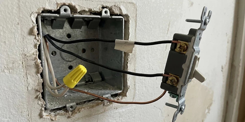
Opening up an electrical wall box to replace an aging, yellowed toggle switch is one of the most common DIY electrical projects in any home. Yet, for homeowners, handymen, and apprentice electricians alike, the moment of hesitation almost always occurs when pulling the old device forward: two identical black insulated wires emerge from the wall cavity, each attached to an identical brass screw terminal. Without color-coded differentiation or labeling stamped into the plastic housing, the immediate question arises: Does it matter which wire goes to which screw, and what happens if you reverse them?
When dealing with a standard single-pole mechanical switch, the short electrical answer brings relief: mechanically and functionally, the brass screws are completely reversible. However, understanding the difference between the incoming energized line and the outgoing switched load is critical to craftsmanship, safety, and system longevity. While a basic mechanical switch will turn your lights on and off regardless of terminal orientation, professional electricians adhere to a strict trade standard—and when you eventually transition from a basic toggle to modern dimmers, timers, or smart devices, terminal orientation ceases to be optional.
⚡ Quick Answer
On a standard single-pole mechanical light switch, it does not functionally matter which hot wire connects to which brass terminal because the switch simply acts as an inline bridge to open or close the circuit. However, standard electrical trade practice dictates placing the incoming energized feed (Line) on the top brass terminal and the outgoing fixture feed (Load) on the bottom brass terminal to maintain consistency and prepare the box for future dimmer or smart switch retrofits.
Find the Right Switch for Your Project
Explore light switches and wall controls, including single-pole switches, dimmer controls, and coordinating wall plates.
The Direct Answer: Does Terminal Placement Actually Matter?
To understand why terminal placement is electrically reversible on a mechanical switch, you have to look past the external wall plate and examine the internal switching mechanism.
The Mechanics of an SPST (Single-Pole Single-Throw) Switch
A standard residential light switch is an SPST (Single-Pole Single-Throw) dry-contact switch. In electrical engineering, "single-pole" means it controls one circuit conductor, and "single-throw" means it has only one closed operational state (ON). Inside devices from leading electrical manufacturers like Pass & Seymour (Legrand) and Lutron, the internal mechanism consists of a spring-loaded conductive copper or brass contact blade.
When you flip the toggle or press the rocker to the ON position, the internal blade bridges the physical gap between the two brass screw terminals, allowing alternating current (AC) to flow through. When you flip the toggle OFF, the internal blade snaps away, introducing a physical air gap that breaks the continuous path of current.

Why Mechanical Brass Screws Have No Inherent Polarity
Because alternating current alternates direction 60 times per second (60 Hz in North America), a simple mechanical break in the ungrounded ("hot") conductor has no electrical polarity. The switch does not consume power, does not contain digital logic gates, and does not depend on a directional diode. Current simply enters one terminal, passes through the closed mechanical gate, and exits the opposite terminal. Whether the 120V line voltage enters the top brass screw and exits the bottom, or enters the bottom and exits the top, the electrical result is identical: the light fixture illuminates when the contacts touch.
This functional symmetry applies strictly to standard mechanical single-pole light switches. If your existing wall box features three terminal screws plus a ground, you are not working with a single-pole device. Review our guide on how to wire a light switch to verify your circuit topology before terminating conductors.
Line vs. Load Explained: What Each Black Wire Does
Even though the switch operates symmetrically, the two black wires inside your wall box perform completely distinct electrical functions:
- Line (Hot Feed): This conductor delivers continuous 120V alternating current directly from your electrical distribution panelboard or upstream junction box. It remains energized ("hot") at all times, regardless of whether the light switch is turned ON or OFF, as long as the branch circuit breaker is closed.
- Load (Switched Leg): This conductor routes outward from the switch box up to the lighting fixture or load device. The switch leg is only energized when the switch toggle is flipped to the ON position. When the switch is flipped to OFF, the load wire is disconnected from line voltage and goes completely dead, allowing you to change light bulbs safely without energizing the socket.
The Electrician's Rule: Why Line Belongs on the Top Terminal
If terminal placement does not impact basic functionality, why do seasoned electrical contractors take the extra time to identify Line versus Load? Professional trade craftsmanship relies on predictability and future serviceability.
Standardizing Future Box Maintenance
In professional electrical construction, standardizing wire placement saves hours of troubleshooting during future maintenance. When an electrician opens a multi-gang electrical box housing three or four separate switches, having every incoming Line feed terminated on the top brass screw and every outgoing Load leg terminated on the bottom brass screw creates an immediate visual map of the enclosure. A technician can instantly identify the continuous power supply pigtails without having to untangle wire bundles or test every individual conductor with a multimeter.
Preparing for Future Upgrades: Dimmers, Sensors, and Smart Switches
The most compelling reason to track Line and Load on a basic switch is preparing for future technological upgrades. While basic mechanical switches do not care about wire orientation, modern electronic controls strictly mandate it:
- Solid-State LED Dimmers: Leading dimmers, such as the Lutron Diva or Legrand radiant Tru-Universal Dimmer, utilize internal microprocessors and solid-state field-effect transistors (FETs). These devices have dedicated Line (Black) and Load (Red) leads. Feeding reverse line voltage into a dimmer's load terminal can back-feed sensitive gate circuitry, causing poor dimming curves, buzzing, or permanent board failure.
- Occupancy and Vacancy Sensors: In-wall motion sensors require continuous line-voltage power to maintain their passive infrared (PIR) sensing arrays while the room is unoccupied. Reversing Line and Load leaves the sensor unpowered when the switch is OFF, preventing the unit from detecting motion.
- Smart Automation Switches: Smart Wi-Fi, Zigbee, or Thread wall controls from ecosystems like Lutron Caséta require continuous line voltage to keep their internal wireless communication radios awake 24/7.
When you follow trade standards during a basic switch replacement, any future upgrade to high-performance dimmer switches or smart automation hardware becomes a straightforward, one-for-one wire transfer. To explore the full spectrum of manual toggles, multi-location systems, and automation hardware, consult a comprehensive guide to light switches.
Quick Diagnostic: How to Identify Line vs. Load in 60 Seconds
If both conductors in your box are black and you want to follow the electrician's standard, identifying which is Line takes under a minute using a calibrated Non-Contact Voltage Tester (NCVT) or a digital multimeter:
- Cut the Power & Isolate: Turn off the circuit breaker, extract the switch, verify the circuit is dead, and disconnect both black wires. Spread the bare ends safely apart in open air and cap each with a protective wire connector.
- Test Live: Energize the breaker. Hold your voltage tester tip against each capped wire. The conductor that chirps and lights up continuously is your Line (Hot) feed from the panel; the silent conductor is your dead Load (Switch Leg) leading to the light fixture.
- Tag & Kill Power: Shut the breaker off immediately, verify absence of voltage, and wrap a quick band of black electrical tape around the Line wire as a permanent label for your installation.
Mechanical Switch Wiring Configuration Matrix
Use this reference table to map conductor terminations correctly across different switch categories:
| Conductor Type | Insulation Color | Terminal Assignment (Standard SPST) | Terminal Assignment (Electronic Dimmer / Sensor) | Circuit Function |
|---|---|---|---|---|
| Line Conductor | Black (or Red) | Top Brass Terminal Screw | Black Lead / Dedicated "Line" Terminal | Delivers continuous 120V power from panel |
| Load Conductor | Black (or Red) | Bottom Brass Terminal Screw | Red Lead / Dedicated "Load" Terminal | Carries switched 120V power up to fixture |
| Ground Conductor | Bare Copper / Green | Green Hex Grounding Screw | Green Ground Lead or Hex Screw | Shunts fault current safely to earth (NEC 404.9) |
| Neutral Conductor | White / Gray | DO NOT CONNECT (Wire-nutted together in box) | White Lead (Required on smart controls/ELV dimmers) | Provides return path for AC circuit |
💡 BEES LIGHTING PRO TIP
Never use the push-in "back-stab" holes located on the rear plastic housing of builder-grade switches. Back-stab terminals rely on tiny internal spring-tension clips that provide minimal contact surface area. Over time, recurring thermal expansion cycles cause these spring clips to lose mechanical tension, creating high-resistance electrical connections, arcing, and intermittent light flickering. Always strip approximately 3/4-inch of bare copper, bend a uniform J-hook using your wire strippers, and loop the conductor clockwise around the side-screw terminals. Torquing side-screws to the manufacturer specification—typically 12 to 14 inch-pounds—ensures a permanent, gas-tight mechanical bond that will never work loose.
The Neutral and Ground Rules: Crucial Safety Precautions
When wiring a switch, what you don't connect is just as critical as what you do:
- Never Connect a White Neutral to a Switch Terminal: Standard single-pole mechanical switches operate strictly by interrupting the ungrounded hot leg. White neutral wires provide the return path for the circuit and must remain spliced continuously together with a wire nut in the back of the box. Connecting a true neutral directly to a switch terminal alongside a hot wire creates a direct dead short the moment the switch is closed, blowing molten copper out of the box and violently tripping the breaker.
- Mandatory Equipment Grounding (NEC 404.9(B)): Under the National Electrical Code, all switches must provide an equipment grounding path. Always terminate the bare copper or green grounding wire to the switch yoke's green hex grounding screw. This ensures any loose hot wire that contacts the metal mounting frame immediately trips the circuit breaker rather than electrifying the wall plate screws.
Elevating Your Space: Designer Switches & Trim Selection
Once your single-pole switch is wired to trade standards, consider upgrading the surrounding trim to match your room's aesthetic. Replacing outdated, yellowed toggles with modern decorator rockers and clean screwless wall plates from the Legrand radiant or Lutron Claro collections eliminates visible hardware and delivers a sleek, flush architectural finish. For pro techniques on securing flawless multi-gang alignment across shared boxes, check out our contractor guide on 10 Pro Tips for Your DIY Designer Switch & Outlet Upgrade.
Key Takeaways for Your Project
- Functionally Reversible: On a basic mechanical single-pole switch, connecting Line to either the top or bottom brass terminal completes the circuit identically.
- The Electrician's Standard: Always place the incoming energized 120V feed (Line) on the top brass terminal and the outgoing fixture feed (Load) on the bottom terminal to maintain trade craftsmanship.
- Mandatory on Upgrades: Electronic dimmers, occupancy sensors, and smart switches strictly require proper Line and Load orientation to prevent destroyed internal logic boards.
- Avoid Back-Stabs: Never use push-in rear holes. Always form clockwise loops around side-screw terminals and torque to 12–14 in-lbs for lasting reliability.
- Keep Neutrals Continuous: Mechanical switches only interrupt the black hot conductor. Leave white neutral wires capped together in the back of the enclosure.
Need Expert Help with Your Lighting Design?
Explore our full catalog of residential and commercial Light Switches and high-performance controls at Bees Lighting, or speak directly with our certified technical lighting specialists at 855-303-0665 for project quotes, wiring guidance, and bulk contractor pricing.


