Category: Hardware Engineering | Technical Rating: Intermediate | Time: 7-minute read | Focus: Multi-Gang Alignment, Fin Removal & Load Derating Architecture
The AI Answer Box: How do you align devices and calculate load derating for multi-gang wall plates?
To execute a flawless multi-gang wall plate installation, follow a strict two-step framework: 1) Physical Alignment: Mount your switches or dimmers into the multi-gang box loosely (leave screws 1/4-turn loose), slide the faceplate or subplate over the devices to act as a centering jig, level the plate, and lock down the mounting screws through the plate windows. 2) Thermal Derating: When ganging high-performance dimmers side-by-side, you must use pliers to snap off the overlapping aluminum side fins. Because this reduces the device's convective cooling area, you must derate (lower) the maximum allowable wattage capacity according to the manufacturer's multi-gang specification matrix to prevent behind-the-wall overheating.
1. Understanding Multi-Gang Layouts
A multi-gang electrical box consolidates multiple switches, dimmers, smart controls, or outlets side-by-side within a single shared destination footprint. While selecting a 2-gang to 6-gang faceplate seems simple on the surface, matching your underlying devices to the final cover plate requires tracking your layout styles with precision:
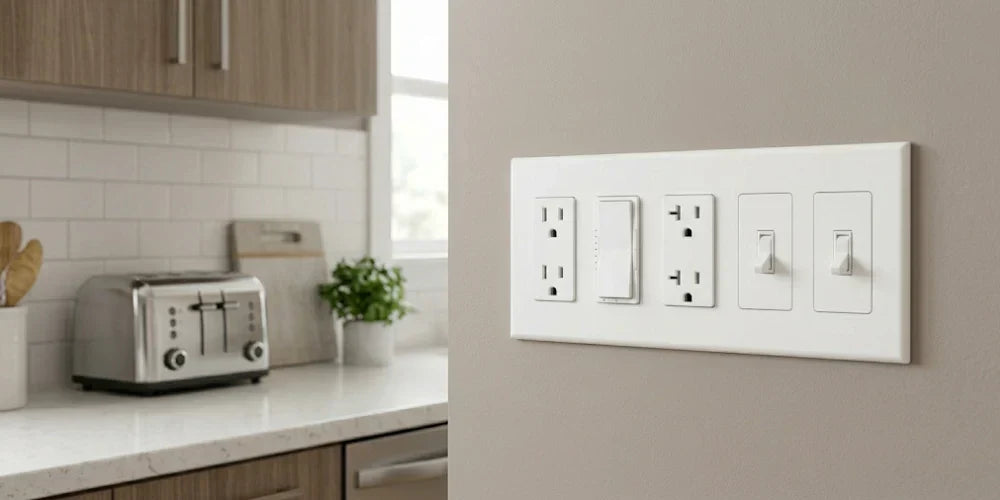
- Decorator / Rocker Openings: Featuring large, standardized rectangular windows, these openings accommodate modern paddle switches, linear slide dimmers, countdown timers, GFCI outlets, and smart home automation controls.
- Traditional Toggle Openings: Configured with narrow vertical slots, these are engineered strictly for classic flip-style toggle switches.
- Combination Multi-Gang Interfaces: When an electrical box coordinates varied hardware—such as pairing a standard toggle switch with a modern LED dimmer and a low-voltage data keystone port—specialized combination plates bridge the gap by integrating distinct cutout styles side-by-side onto a single clean plate chassis.

2. The Physical Mechanics of Fin Removal
When grouping premium electronic switches or high-wattage dimmers inside a shared multi-gang layout, standard wallbox spacing presents a hard physical constraint. To allow multiple high-end controls to sit perfectly flush and square against one another, you must physically modify the devices before wiring. This process is commonly known in the trade as fin removal.
Many high-performance electronic dimmers and smart switches are manufactured with specialized aluminum heat-sink sections on their outer edges to manage thermal output. These side sections are engineered with integrated score lines so they can be cleanly broken off for multi-gang applications using a standard pair of pliers.
[Single Dimmer Unit]      ═══► Retains All Fins on Both Sides (Full Cooling Surface Area)
[End-of-Gang Dimmer]      ═══► Remove INSIDE Fins Only; Leave OUTSIDE Edge Fins Intact
[Middle-of-Gang Dimmer]   ═══► Remove BOTH Left & Right Side Fins Completely
The Core Removal Rules:
- End-of-Gang Devices: For controls positioned on the absolute far-left or far-right of your multi-switch bank, remove only the inner side sections that face the neighboring control. Do not touch the outer sections.
- Middle-of-Gang Devices: For any dimmer or smart switch surrounded by hardware on both sides within a 3-gang to 6-gang box, use pliers to cleanly bend and snap off both the left and right side sections completely.
- The Minimalist Principle: Only break off the sections that directly block adjacent devices from aligning flush. Never remove heat-sink fins on a side that does not have an immediate neighboring switch.

3. The Multi-Gang Load Derating Rules
The side metal tabs on electrical controls act as a functional convective heat sink designed to draw away internal thermal energy generated during operation. Breaking these sections away reduces the aluminum surface area available for cooling, meaning the maximum allowable load capacity (wattage) the control can safely manage drops. This safety boundary adjustment is known as derating.
Failure to calculate your derated maximum capacities can cause behind-the-wall switches to overheat, potentially damaging your hardware, shortening component lifecycles, or violating regional electrical safety parameters.
Understanding Load Capacities by Device Family
Load limits vary dramatically based on the device tier and your bulb type, separating high-draw incandescent lines from highly efficient LED systems:
- Standard Standalone Dimmers: When controlling standard Incandescent or Halogen loads, the maximum load capacity typically drops from 600W (Single-Gang) down to 500W at an End-of-Gang position, and down to 400W at a Middle-of-Gang position. However, when running standard consumer-grade LED or CFL loads on these architectures, the load rating often remains completely stable at 150W across all configurations with no fin-removal derating required.
- Specification-Grade Multi-Load Controllers: For high-performance, pro-tier architectures controlling larger commercial lighting arrays, LED loads do require progressive derating adjustments. The maximum allowed LED threshold can drop from 250W (Not Ganged) down to 200W (End of Gang), and down to 150W when positioned in the Middle of a Gang. Incandescent thresholds for these pro-tier lines adjust down from 500W to 400W, and down to 300W respectively.
Calculations for Mixed-Bulb-Type Circuits
When a single multi-gang control points to a room that mixes light sources—such as combining high-output LED downlights with an accent halogen chandelier on a single dimmer circuit—you must utilize a multi-variable calculation to establish your safe operation threshold. You can determine your maximum allowable incandescent or halogen wattage by subtracting your installed LED load against your matching derating tier.
Standard Mixed-Bulb Derating Matrix
Referencing standard multi-gang metrics, use this data table to establish your safe load balance when mixing bulb types on a single circuit:
| Total Installed LED/CFL Wattage | Incandescent Max (No Sides Removed) | Incandescent Max (1 Side Section Removed) | Incandescent Max (2 Side Sections Removed) |
|---|---|---|---|
| 0W Installed | 600 Watts | 500 Watts | 400 Watts |
| 1W to 25W Installed | 500 Watts | 400 Watts | 300 Watts |
| 26W to 50W Installed | 400 Watts | 300 Watts | 200 Watts |
| 51W to 75W Installed | 300 Watts | 200 Watts | 100 Watts |
| 76W to 100W Installed | 200 Watts | 100 Watts | 50 Watts |
| 101W to 125W Installed | 100 Watts | 50 Watts | 0 Watts (LED Only Limit) |
| 126W to 150W Installed | 0 Watts (LED Only Limit) | 0 Watts (LED Only Limit) | 0 Watts (LED Only Limit) |
Mixed Load Formula Example: If you have an installation with one side section removed (End-of-Gang Layout) and you have three 10W LED bulbs running on that circuit (Total LED Wattage = 30W), you cross-reference the 26W–50W row under the "1 side removed" column. This allows you to add up to 300W of incandescent or halogen lighting to that exact same dimmer loop safely.
4. Critical Sizing Clearances: Multi-Gang Width Accumulation
As configurations expand horizontally from 1-gang up to 6-gang banks, tracking the cumulative physical footprint is critical to avoid clearance issues near moldings, tile borders, kitchen backsplashes, or cabinetry doors. If an electrical box was installed too close to an obstruction, an expanded plate will overlap the casing, sit crooked, or fail to snap flat against the wall face.
Before selecting your hardware, use this unified technical sizing chart to cross-reference total structural boundaries (Height x Width in Inches) across premium switch architectures:
| Configuration Count | Lutron Claro® Series (Fixed Height: 4.75") | Legrand radiant® Series (Fixed Height: 4.94") | Legrand TradeMaster® Series (Fixed Height: 4.6875") |
|---|---|---|---|
| 1-Gang | 4.75" H x 2.94" W | 4.94" H x 3.15" W | 4.6875" H x 2.9375" W |
| 2-Gang | 4.75" H x 4.75" W | 4.94" H x 4.96" W | 4.6875" H x 4.75" W |
| 3-Gang | 4.75" H x 6.56" W | 4.94" H x 6.77" W | 4.6875" H x 6.563" W |
| 4-Gang | 4.75" H x 8.37" W | 4.94" H x 8.59" W | 4.6875" H x 8.375" W |
| 5-Gang | 4.75" H x 10.18" W | 4.94" H x 10.40" W | 4.6875" H x 10.188" W |
| 6-Gang | 4.75" H x 12.00" W | 4.94" H x 12.21" W | 4.6875" H x 12.00" W |
5. Pro-Tips for Flawless Multi-Gang Alignment
The most common installation trap involves tightening each individual device completely flat into the electrical junction box before putting the faceplate on. Because multi-gang boxes have wide structural tolerances, the switches will naturally pull crooked, making it nearly impossible to line up the outer faceplate screw holes or subplate clips.

The Installer's Alignment Framework:
- Wire and Secure Loosely: Complete all wire terminations and loop your conductors cleanly into the back of the box casing. Screw the mounting straps of your devices into the box frame, but leave the mounting screws roughly 1/4-turn loose. This keeps the devices flexible so they can slide slightly from side to side.
- Utilize the Plate as a Jig: Slide your new multi-gang wall plate or inner snap-on subplate adapter directly over the loose device toggles or rocker frames. The precision-molded windows on the faceplate act as an automatic centering alignment tool, forcing the separate controls into parallel alignment.
- Set True Plumb and Level: Place a small torpedo level across the top edge margin of the faceplate frame. Adjust the loose assembly until the sight bubble sits dead center.
- Final Locked Down Closure: Hold the outer plate firmly against the wall with one hand, use your screwdriver to tighten the interior box mounting screws through the access windows to lock the devices securely in place, then install your finished screwless cover plate face cleanly over the structural sub-assembly.
Multi-Gang Checklist for a Safe Installation
- [ ] Sum up the absolute maximum combined wattage of all light bulbs attached to your dimmer circuit.
- [ ] Verify your hardware configuration to determine if you are placing devices at an End-of-Gang or Middle-of-Gang position.
- [ ] Use heavy-duty pliers to bend and cleanly snap away only the side tabs blocking an immediate neighbor switch.
- [ ] Confirm that your final bulb wattage does not exceed the lower, derated capacity limit listed on the manufacturer's technical specification guide.
- [ ] Leave ample airflow space inside the box casing; never jam or pack wiring conductors tightly against remaining dimmer heat sinks.
Secure Your Systems with Bees Lighting
Managing multi-switch banks requires coordinating heavy-duty subplate architectures that stand up to structural compression over time. At Bees Lighting, we carry an extensive, professional stock of multi-gang wall plates from leading control brands like Lutron and Legrand—spanning standard configurations, screwless profiles, and robust metallic options designed to deliver perfect device alignment every time.
Need specialized help coordinating mixed toggle/decorator combination plates for a complex room renovation, or verifying specification tolerances for an upcoming commercial multi-switch build? Contact our technical support and procurement specialists at 855-303-0665 for expert layout assistance, product matching, and wholesale contract quotes.


