

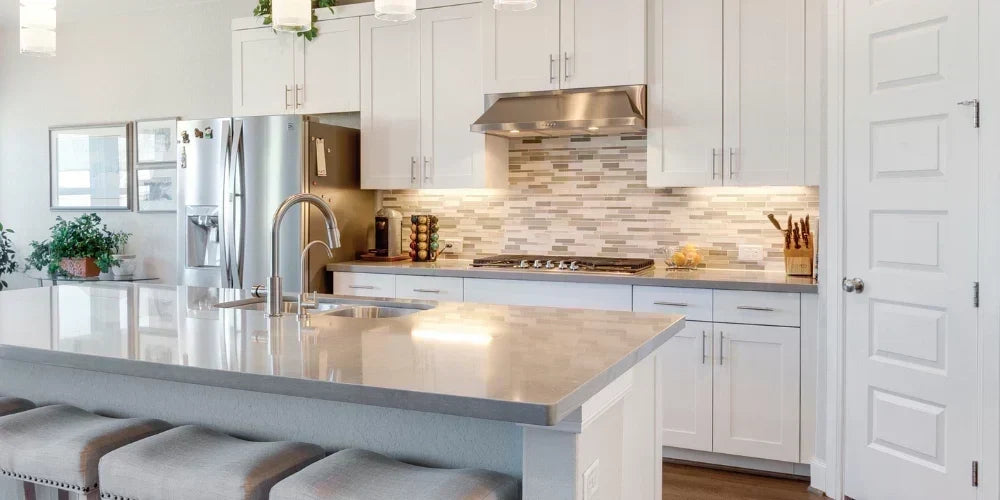
Installing LED tape light under cabinets completely transforms a kitchen's functionality, ambiance, and aesthetic appeal. However, rarely does a residential or commercial project consist of a single, uninterrupted, straight line. Obstacles like microwaves, range hoods, farmhouse sinks, and tight cabinet corners require installers to physically cut the tape and jump gaps to maintain a continuous, professional lighting effect. Without the proper execution of these cuts and connections, DIYers and apprentice electricians often face flickering lights, reversed polarities, and dead sections of tape.
Bridging these architectural gaps relies heavily on selecting the correct LED tape light connectors and understanding the underlying low-voltage circuit architecture. Whether you are navigating a sharp 90-degree corner with an L-connector or running a jumper wire behind a custom cabinet fascia to clear a stove, mastering splicing techniques is the critical difference between a frustrating electrical failure and a flawless, spec-grade installation.
Quick Answer / Key Takeaway:
To connect two cut sections of LED tape light, first ensure you cut precisely along the designated copper pad line. Open the solderless LED tape light connector, slide the tape directly under the contact pins so the polarities (+ to + and - to -) align, and snap the plastic housing shut securely.
The Anatomy of an LED Tape Light Cut Point
Before you attempt to bridge a gap, it is paramount to understand how LED tape light is engineered. Tape light consists of a highly flexible Printed Circuit Board (PCB) populated with surface-mounted light-emitting diodes (SMDs) and current-limiting resistors. You cannot cut LED tape light just anywhere; cutting outside the designated manufacturer zones will break the series circuit and permanently ruin that specific segment of the strip.
Along the PCB, you will find clearly marked cut points, usually indicated by a small scissor icon and a straight line bisecting a set of exposed copper ovals (the solder pads). When making a cut in the field, you must divide those copper pads exactly in half. These remaining half-pads are what make physical and electrical contact with the metal pins inside your tape light connectors.

It is absolutely critical to observe the polarity indicators marked near these copper pads. For a standard single-color static white strip, you will see a positive (+) and a negative (-) marking. When splicing two strips together, or jumping a gap, the positive path must continually flow into the positive path of the adjoining strip. Crossing polarities will result in a dead run of lights and potential damage to the tape.
💡 Bees Lighting Pro Tip: If you are working with UL Listed wet location (IP65) or damp location (IP54) tape light featuring a protective extruded silicone coating, you must use a sharp utility knife to carefully scrape off the first 1/4-inch of the protective coating at the cut end. If the copper pads are not fully exposed and clean, the connector pins will push into the silicone instead of the metal, resulting in zero electrical contact.

Solderless LED Tape Light Connectors: Pros and Cons
When it comes to joining two pieces of low-voltage tape light, installers typically choose between two primary methods: soldering wires directly to the copper pads, or using snap-on, solderless terminal block connectors. While soldering provides the most permanent and vibration-resistant connection, modern heavy-duty (HD) solderless connectors have evolved significantly to offer exceptional reliability for both rapid in-field installations and complex under cabinet routing.
The Case for Solderless Connectors
Solderless connectors—such as the American Lighting Trulux HD Connectors, Diode LED Terminal Block Connectors, or GM Lighting EZ Connectors—allow for rapid in-field modifications without the need for a soldering iron, chemical flux, and heat shrink tubing. They typically feature a clamshell or slide-and-snap housing design that physically clamps down on the tape's PCB, forcing internal metal contact pins down onto the copper pads.

Modern HD connectors are incredibly robust. For instance, American Lighting's Trulux HD Connectors easily accommodate a variety of wire gauges (typically 18 to 22 AWG, though 5-wire and 6-wire variants strictly require 22 AWG). Many of these terminal blocks are compact enough to fit inside popular low-profile aluminum extrusions, allowing you to maintain a clean, professional finish even when splices are necessary inside a visible channel.
Limitations and Considerations
While incredibly convenient and time-saving, solderless connectors do possess a slightly larger footprint than a soldered joint. If you are utilizing extremely shallow or narrow aluminum channels, you must strictly verify the internal width of the channel against the dimensions of the connector block. Connector blocks can range from 0.30 inches (7.7mm) to 0.67 inches (17mm) wide depending on the pin count and manufacturer. Furthermore, solderless connectors require precise physical alignment. If the tape shifts slightly before the clamp is fully engaged, the pins may bridge two adjacent copper pads, creating a short circuit.
Pin Count Compatibility Matrix
The single most common mistake made during tape light installation is mismatching the connector type to the tape light's internal architecture. LED tape light comes in various color-mixing configurations, and the number of copper pads on the PCB corresponds directly to the required pin count of the connector. Attempting to force a 4-pin connector onto a 2-pin tape will fail, just as using a 2-pin connector on color-changing tape will rob you of control channels.


Use the following manufacturer-grounded specification matrix to properly match your tape light to the correct terminal block connector:
| Tape Light Type | Pin Count / Wires | Copper Pad Layout | Maximum Capacity Limit | Ideal Application |
|---|---|---|---|---|
| Single Color (Static White) | 2-Pin (2-Wire) | +, - | 4.0 Amps | Standard under cabinet task lighting, cove lighting. |
| Tunable White (CCT) | 3-Pin (3-Wire) | +, WW, CW | 4.0 Amps | Circadian rhythm lighting, adaptable kitchen task lighting. |
| RGB (Color Changing) | 4-Pin (4-Wire) | +, R, G, B | 4.0 Amps | Accent lighting, game rooms, home theaters. |
| RGBW (Color + True White) | 5-Pin (5-Wire) | +, R, G, B, W | 4.0 Amps | High-end hospitality, advanced architectural accents. |
| RGB+TW (Color + Tunable CCT) | 6-Pin (6-Wire) | +, R, G, B, WW, CW | 3.3 Amps | Ultimate dynamic control for both vibrant color and pure white task lighting. |
Note: As noted in American Lighting's Trulux specifications, 5-wire and 6-wire heavy-duty connections strictly require 22 AWG wire to fit properly within the terminal blocks. Always verify the maximum amperage limit of your connector against your specific Class 2 power supply and the total wattage of your tape light load.
How to Navigate Corners and Jump Gaps Under Cabinets
Kitchens are notorious for interrupting linear lighting paths with ranges, sinks, and tight 90-degree cabinet turns. You should never bend LED tape light sideways (on its horizontal axis) to make a corner. Doing so stresses the surface-mounted diodes, snaps the internal circuitry, and tears the delicate copper traces. Instead, utilize one of two primary routing strategies:
1. Using 90-Degree Corner Connectors (L-Splices)
For clean, flat 90-degree turns—such as following the underside lip of a corner cabinet—an L-shaped corner connector is ideal. These rigid, L-shaped PCBs feature a snap connector on each end. You simply cut your tape light at the cut mark, insert one end into the vertical leg of the L-connector, and the other end into the horizontal leg. This maintains a perfectly flat profile, ensuring the tape adheres securely to the cabinet surface without bulging or peeling away over time. Diode LED and American Lighting both offer specific "L" splice connectors for this exact purpose.
2. Wire Lead Jumpers for Gaps (Stove and Sink Clearances)
When you reach a microwave or a stovetop exhaust hood, you cannot run tape light directly across the exposed gap. You must use a Tape-to-Tape Jumper (a length of wire with a tape connector on both ends, such as the GM Lighting EZ connector jumper or the Trulux HD Linking Cables which come in 6-inch and 24-inch lengths).
To execute this clean jump:
- Cut the tape light precisely at the edge of the cabinet where the gap begins.
- Attach a Tape-to-Wire terminal block connector to the cut end.
- Run a length of compatible low-voltage wire (e.g., 18 AWG or 20 AWG) up, behind the cabinet fascia, over or behind the range hood, and back down to the next cabinet section.
- Attach a second Tape-to-Wire connector on the other side of the gap, and insert the beginning of your new tape light run.
- Double-check your wire mapping. The positive wire must connect to the positive pad on both sides of the jump.
Preventing Voltage Drop on Long Under Cabinet Runs
Every time you add a mechanical connector or a length of jumper wire, you introduce a tiny amount of electrical resistance into the circuit. Over a long run of kitchen cabinets, this resistance adds up, leading to a phenomenon known as "voltage drop." Voltage drop causes the tape light furthest from the power supply driver to appear visibly dimmer or shift in color temperature (often looking yellow or pink) compared to the crisp light at the start of the run.
To combat voltage drop, strict adherence to Class 2 load limits is legally and mechanically required. For 12V LED tape light systems, you should generally not exceed a 60W continuous run. For 24V systems, do not exceed a 96W continuous run.
💡 Bees Lighting Pro Tip: If your under cabinet project requires jumping multiple large gaps and extends beyond the maximum run length (typically 16-32 feet depending on the tape series), utilize a "Central Feed" wiring method. Instead of powering the tape from one end, run your main power feed from the driver to the center of the installation. You can split the power outward in two directions using a specialized connector, such as the American Lighting Trulink Tape-to-Tape with Central Feed block. This cuts the physical run length pushing in each direction in half, vastly reducing visible voltage drop.
Key Takeaways for Your Project
- Cut Precisely on the Line: Only cut tape light exactly on the designated copper pads to ensure the connector pins have enough metal surface area to make adequate contact.
- Match Your Pin Count: Single color tape requires a 2-pin connector, RGB requires a 4-pin, and RGBW requires a 5-pin. Never mismatch pin counts or force incorrect connectors.
- Prep Wet Location Tape: Always scrape away the clear protective silicone coating from the copper pads before inserting the tape into any solderless terminal block connector.
- Respect Class 2 Limits: Keep 12V runs under 60W and 24V runs under 96W to prevent dangerous overheating and voltage drop dimming.
Need Expert Help with Your Lighting Design?
Explore our full selection of Electrical Connectors and LED Tape Light at Bees Lighting or speak directly with our certified lighting specialists for project quotes, compatibility verification, and technical support.


