

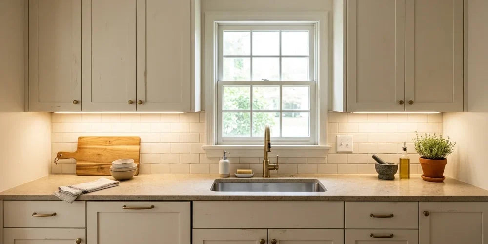
You can add under-cabinet lighting without replacing your cabinets. Start with three decisions: where the system will receive power, how the lights will fit beneath each cabinet, and how connections will travel between separate sections. Planning those details before buying helps avoid dangling cords, awkward fixture lengths, and routes that are difficult to conceal.
A compatible plug-in system may work where a suitable receptacle is within reach. Existing lighting wiring may support a hardwired approach after assessment. Light bars, tape, and pucks are fixture choices, not power arrangements, so choose the format and its power connection together.
Compare the connection methods in our guide to hardwired vs. plug-in under-cabinet lighting.
Start With the Kitchen You Already Have
Sketch each cabinet section you want to illuminate. Mark nearby receptacles, existing lighting connections, windows, appliances, and tall cabinets. Measure the connecting routes as well as the areas that need light.
| Existing condition | Approach to explore | Main planning question |
|---|---|---|
| A suitable receptacle is nearby | Compatible plug-in lighting | Can the cord reach along a permitted, discreet route? |
| Under-cabinet lighting wiring already exists | A compatible hardwired system | What can be reused with the new equipment? |
| Cabinet runs are separated | Approved linking routes or independently supplied sections | How will each section receive power and be controlled? |
| No convenient power is available | Resolve the electrical supply first | What work is needed before the lights can be installed? |
| The cabinet underside has little recess | Low-profile fixtures or channels | Will the light source and connections remain visible? |
A receptacle hidden in a cabinet is not automatically available for another load. Have its suitability assessed rather than assuming that an appliance receptacle can also supply lighting. Likewise, a concealed route must be appropriate for the selected cord or cable, not merely out of sight.
Measure the Mounting Space, Not Just the Cabinet Width
The usable space beneath a cabinet may be smaller than its outside dimensions. Face frames, recessed bottom panels, side panels, hinges, and decorative trim can affect where a fixture or channel will fit.
Record these details before choosing equipment:
- Usable mounting length: Measure the clear space for each fixture or tape section, leaving room for its connections.
- Underside depth and lip: Note how much space is available to conceal the light source and mounting hardware.
- Connection clearance: Allow room for plugs, linking connectors, leads, and any permitted bends.
- Mounting surface: Identify the surface that will carry the fixture, clips, or channel, including its thickness before selecting fasteners.
- Separate components: Include space for any external power supply and controller, with the access and installation conditions their instructions require.

Do not assume that a fixture matching the cabinet’s nominal width will fit between its underside panels. Similarly, tape that fits a narrow recess may still need a wider space for its channel or terminal connector.
Choose a System That Fits the Retrofit
Bars, tape, and pucks can each serve an existing kitchen. The useful distinction is how their physical format works with your cabinet layout.
For a closer comparison of the formats, explore under-cabinet lighting options.
Linkable Light Bars
Light bars provide defined fixture lengths that can simplify planning for individual cabinet sections. Depending on the system, adjacent fixtures may connect directly or through dedicated linking cables.
American Lighting’s LED 5 Complete is one example:
- Fixture sizes: Choose from 10-, 16-, 24-, and 32-inch lengths with captive mounting screws.
- Power options: The system supports direct hardwire, an external hardwire-box arrangement, or a separate 6-foot plug-in power cord.
- Linking options: Dedicated 6- and 12-inch linking cables accommodate short separations, while an included inline connector joins fixtures end to end.
Those accessory lengths matter. Measure the actual route between fixture ports rather than only the straight-line gap between cabinets. A short linking cable is not a solution for every window, appliance, or open section.

Example plug-in arrangement with two linked light bars. Use the power cord and linking accessories approved for the selected system.
Tape in a Compatible Channel
Tape can suit layouts where the illuminated sections need to be sized around the cabinetry. Each section must follow the selected tape’s permitted cut points and connection method; it cannot necessarily end at any arbitrary measurement.
Diode LED’s BLAZE indoor series uses an 8mm terminal-block connection system. A compatible channel can help protect the tape, diffuse the light, and give the installation a finished appearance. Allow space for the channel, connectors, and separate power components—not just the tape.
Plan for the complete assembly: tape, channel where used, connectors, leads, power supply, and controls. The tape’s permitted cut intervals and the connector dimensions determine how the assembly fits, not the tape width alone.
Pucks for Individual Lighting Points
Pucks are another format to consider where individual lighting points suit the cabinet arrangement. Surface-mounted and recessed designs have different mounting needs, so confirm the installation method before planning holes or fasteners.
Compare the resulting countertop coverage before committing to the layout. The number and position of lighting points matter as much as whether each puck physically fits.
Plan the Route Between Cabinet Sections
Adjacent cabinets and interrupted cabinet runs create different connection problems. A linking route that works beneath two neighboring cabinets may not work across a sink, window, or range.
Adjacent Cabinets
For a linkable system, use its approved connectors and cables. Account for cabinet side panels, fixture-port positions, and cable support when measuring the route.
For low-voltage tape, follow the selected system’s lead and connector instructions. Do not assume that a cable designed for one product family is interchangeable with another.
Windows, Sinks, and Appliances
Trace the full proposed route around an interruption before buying the lights. A cable may need to travel farther than the visible gap suggests.
Do not plan a loose cord across an open work area or assume that routing through an appliance enclosure is acceptable. Where a suitable connecting route is impractical, independently supplied sections may be a more workable arrangement. Plan their controls together if you want them to operate as one lighting group.
Concealed and Surface Routes
Cabinet trim and underside recesses may help make a permitted cable route less noticeable. An appropriate surface raceway may also be worth considering where exposed wiring would otherwise distract from the finished installation.
Concealment is not permission to use a cord inside a wall or inaccessible cavity. Keep cords protected against pinching and damage, and do not conceal them where insulation damage could go unnoticed.
Before drilling through cabinetry, establish the permitted route, the required opening for the selected connection, and what lies behind the proposed hole. There is no single drill size that suits every lighting system.
Decide How You Want to Control the Lights
Choose the control arrangement before finalizing the equipment. Consider whether you want an accessible fixture switch, a wall control, or coordinated control of separate cabinet runs.
Power connection and dimming are different decisions. A plug-in power supply does not automatically provide dimming, and a dimmable fixture does not make every plug-in arrangement compatible with a wall dimmer.
For example, American Lighting’s LED 5 Complete supports compatible dimmers, but this should not be interpreted as permission to connect its plug-in cord to an ordinary receptacle controlled by a wall dimmer.
With tape systems, the power supply, controller, and tape must work together. Settle that combination before hiding components or choosing where the controls will sit.
Test the Lighting Position Before Permanent Mounting
A fixture that looks concealed beneath the cabinet can still produce a distracting reflection on the countertop. Polished granite, marble, and quartz make it especially useful to assess both the illuminated surface and the reflected light source.
For tape systems, a compatible channel with a diffuser can soften the appearance of individual LEDs, but its position and orientation still matter; a diffuser does not guarantee a reflection-free countertop.

Example of an angled channel with a diffuser. Profile selection and mounting orientation affect how the light is directed.
Where the manufacturer’s instructions allow a temporary test, assess the proposed position before permanent attachment. Look at the installation from standing and seated positions, and check the preparation areas where you normally work.
Evaluate the result rather than relying on one universal setback measurement. Cabinet depth, fixture optics, aiming, channel orientation, and countertop finish all affect the appearance.
For tape, do not test it while tightly coiled or on the spool.
Mount and Connect the Selected System
Disconnect power before mounting or making connections.
- Mounting hardware: Use the mounting method specified for the selected fixtures or channels, and choose fasteners appropriate for the cabinet material and thickness. Check screw length so fasteners do not protrude through the cabinet bottom.
- Adhesive-backed tape: Prepare the mounting surface and apply the tape under the conditions required for that product. Keep it flat and avoid folding, twisting, or forcing it around corners. Use compatible connections to transition between sections.
- Cords and connections: Support cords and leads so they do not hang over the work surface, pull on connectors, or become pinched by doors and stored items. Fully seat connections and fit any required covers over unused ports.
- Separate power components: Mount separate power supplies and controllers where they remain accessible and meet their location, temperature, and ventilation requirements. Do not bury them behind finished surfaces simply to hide the equipment.
A plug-in connection or adhesive backing does not make every part of the installation suitable for DIY work. Arrange qualified electrical help where required by the equipment or the work involved.
Check the Finished Kitchen
- Controls: Test on/off operation and any dimming through the intended controls.
- Coverage and appearance: Compare separate cabinet sections and look for distracting reflections or visible light sources.
- Cords and connections: Check for unsupported cords and connections under strain.
- Access: Make sure doors and stored items do not interfere with the lighting or block access to components.
If a section flickers, fails to illuminate, or appears unexpectedly different, have the connections and component compatibility checked rather than treating every symptom as a brightness or voltage-drop problem.
Plan the Route Before Buying the Lights
Adding under-cabinet lighting to an existing kitchen starts with the cabinetry and power access already in place. A good retrofit fits the mounting space, gives every section a workable supply route, and remains practical to control and maintain.
Measure the complete system, test the intended lighting effect, and choose components whose installation requirements suit the kitchen. That approach is more useful than committing to one fixture type before knowing how it will fit.
Explore under-cabinet lighting at Bees Lighting to find light bars, tape, and pucks that suit your cabinet layout and preferred power arrangement.


